Friday, June 15, 2018

Getting the lead out . . .

Why is lead so doggone heavy?
That's a rhetorical question. Please don't respond with answers.

Anyway, I have a type case full of lead spacing slugs, and it is so heavy I almost can't lift it. I wanted to divide the contents into two separate cases, but a lead case is not easy to find.

As luck would have it, I found one on eBay and ordered it. But what I received was a California job case full of sea shells. Yikes. This is a travesty. This type case is very embarrassed.


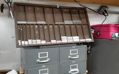
I finally swapped that case for a lead case, and installed it today in my print shop.

Wooden type case for lead spacing


Anthropomorphism
It's fastened to the wall and to the metal cabinets and tilted slightly backward. This type case is happy because it's doing what it's supposed to do.

You just can't have enough type cases
Well, you really can, and I'm at my limit with 30 of them. I've created a fully-functioning type cabinet in the knee space of these old disco-look cabinets I found on the street (at Emory Medical Center).

Just install some steel angles for drawer slides, and you're on your way. Suddenly, I have 13 additional type cases and 13 reasons to get more type.

I think this cabinet is a good match for the pink and black and blue cabinets. Stay tuned for more from Factory Press.


Friday, April 20, 2018

Printing cards on old Kelsey presses


OK, I'm totally involved with letterpress printing (again). With the Kelsey 3X5, 5X8, and 6X10 presses, I think I have a good range of clam-shell platen presses.


Mistakes never end
And each day, I learn from my mistakes, then make new mistakes that break my heart.

Printing 320 cards with a 50% success rate
Here's a recent project for the APA printing group that requires a ransom of four bundles (160 cards each) of letterpress-only cards per year.

These cards (or book marks) employ two handset typefaces, two ornamental borders, and a photo polymer graphic made from an old, public-domain image.


The face (black ink) was printed on the 6X10 Kelsey after I learned a few more things about how a .03-inch height difference can ruin an entire day. The purple back side shows my logo with my name, as required by the APA. It was printed on the smaller 5X8 press (see below).


Let's all say "recto"
For those who are interested, the front of a page is "recto" and the rear of a page is "verso". Seems backwards, doesn't it?


The 5X8 Kelsey press
Probably the most popular of all the Kelsey presses, this is a workhorse for smaller cards. Here's the printer's view of a rear card face (verso, remember?) with the purple-inked rollers and ink disc.

Please note the silvery aluminum chase that I manufactured.


Cornering the market
I have been buying up all the retro record racks I could find (at a cheap price). Turns out they are perfect drying racks for cards—small, light, portable, and easy to store.


Sunday, March 11, 2018

Reviving an 1870s printing press (part 4)

Part 4
Will it print?

If you want the short answer, it's NO, it will not print—at least, not yet. I remain positive in spite of what you're about to read.

My wife and I moved this heavy press from my repair-the-press shop to my print shop. I installed a 6X10 Kelsey chase from a later-model Excelsior, and dammit, it was too tall. The top of the chase extended above the roller tracks by a huge margin. The picture below will rip your heart to shreds.

Two troubling options
I had to cut away part of the chase, or try to make it sit lower in the press. Not wanting to compromise each of my three chases, I decided to to try to lower the chase supports. Here's what I'm dealing with:


If you recall, the chase supports are two steel angles epoxied to the bottom edge of the chase bed.


I measured again and calculated again and carefully determined (guessed) that the chase should be lowered by .625 inches. This would keep the printing area (open area) of the chase on the chase bed, and would also eliminate the interference with the rollers.

Epoxy upon you
I also learned that sticking the angles to the back of the bed didn't work because their 1/8" thickness (on the back) tilted the bed out of its parallel relationship with the platen. Why didn't I think of that earlier?

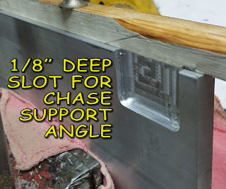
Solution: Cut recesses (pockets) into the back side of the bed so everything would be flush. And of course, this required a thicker chase bed. I went from 3/8" to about 1/2".

During this little episode, I learned that the J-B Weld epoxy is really, really strong. I could not remove the angles from the old chase bed. But I've since learned that epoxies do not like really tight clamping; instead, a tiny bit of thickness is best for the epoxy bed.

Here's the new chase bed with one of the slots. The wooden spacer strip moves the angle flange exactly 5/8" (.625"). The second photo below shows the angle clamped into the pocket. Keep in mind that this is the bottom edge of the chase bed.


Bottom edge (upside-down) of chase bed in vise, with angle embedded in epoxy
and clamped to back side of  chase bed


Next: Testing the new chase bed and waiting for the next problem to slap me down


Tuesday, March 6, 2018

Reviving an 1870s printing press (part 3)

Part 3
Reworking (or replacing) the spring-loaded clamp bolts
Before we get to that: On my press, the roller arms are not centered on the chase bed, and the left arms literally drag along the roller track. On the right side, the clearance is about 1/4" inch. I guess in a perfect world, the clearance on each side should be about 1/8", but with the several breaks and welds on my press, I'm glad the various parts still move at all.

This excellent photo shows the interference between the parts:


Don't try to bend cast metals
I didn't even consider trying to adjust this tight fit by bending or heating. I resorted to an old-school method.
Several authoritative strokes with a good file removed a few thousandths of an inch from the arm and from the track and now things move smoothly and without that dreadful dragging sound.

The spring-loaded clamp bolts
These bolts are designed to lock onto tabs on the original closed-bottom chase, and I think Kelsey did a pretty good job in that area.

Here's a picture from Alan Runfeldt's Excelsior Press blog (something to check out if you love old printing presses). The chase has a tab on each side to lock into the spring bolts.


This chase would be pushed downward along the chase-bed and would engage two large-flange spring-loaded bolts. The flanges would lock the tabs against the bed.


Note: When I started this project, I had no idea how this chase looked or how the bolts would clamp it down, thus my complicated drawings and dimensions in part 1 of this story.

Many thinks to Alan Runfeldt for his expertise and advice and photos to guide me in a better direction.

The next two photos show the bolts on my press. In the first one, I'm pressing the bolt as far as it will go (spring fully compressed at my finger). It extends a bit more than 1-1/8",  which is exactly right for a chase of 3/4" thickness and my home-made chase bed of 3/8" (The math: 3/4" = 6/8", plus 3/8" equals 9/8" equals 1-1/8").


This second photo shows the opposite (left) end with my chase bed clamped with the bolt flange (bolt head). There's still lots of room for the bolt to extend and grab the chase.


Cautions
I noticed that these spring bolts interfered with the motion of my press unless the chase bed (that I made) was clamped on the base. If not, the opposite ends of the bolts will block the frame of the press as it moves to print.
The solution, of course, is to always have the chase bed installed, and there's no reason not to.

Another problem may be specific only to my press with its welds and distortions. A newer 6X10 chase would not fit between the bolts. I had to reduce the diameter of each bolt by about .05 inches. This is an easy task with the old cast-iron (I think) bolts. They file and machine like graphite.
But they are brittle, and I broke one—so I bought some 1/2" X 2-1/2" carriage bolts and filed one down to make a new bolt with a somewhat smaller shoulder. I machined the crown on the head to match the existing bolt (if you don't look too closely). The head of the carriage bolt has a diameter of one inch, exactly the same as the Kelsey bolt head.


The next step
At this stage of the game, I'm pretty sure that this monster can be brought to life and can be used as more than a door stop. With that in mind, I have placed an order for two 6X10 ink rollers. We will soon know.

Next: Will it print?


Reviving an 1870s printing press (part 2)

Part 2
Making things harder than they should be
If you read part 1 of this fascinating series, you know that I had to make a chase base for a 19th-century letterpress machine.

I started by measuring every part of the press that would hold the new chase bed. The goal was to have a press that would eventually use a standard open chase that would bypass the hard-to-get closed chases.

Here's a bit of my sketching and dimensioning and notes and corrections, all scribbled on two sheets of my Department of the Navy memo pads.


A simple approach
After a few days of making prototypes from plywood and trying to make things fit, I realized I was doing more work than necessary; all I really needed was a simple rectangular base. 

NOTE: Some of the following information is not correct if you use newer 6X10 chases for later Kelsey presses (as I did). See my later blog (part 4) about lowering the chase. JHS

If you're doing this at home, the size should be about 6.75" X 11.625", and about 3/8" thick. I used aluminum. It will look something like this when mounted in the press (without the chase). You should see two cast-iron shoulders that support and position the chase base. They are located near the center of the bed, a few inches apart. They are hidden in this view.

The chase will be supported by two steel angle tabs, visible at the bottom-left and -right of the base. These two tabs are the exposed legs of steel 1" X 1" angles, cut about 2-inches long. I used J-B Weld epoxy to attach them to the back of the chase. See more details below:

Position the two angles to avoid conflict with  two cast-steel shoulders on the base.
The aluminum base is resting on and hiding these shoulders in this photo.


.

Details of the steel angles for supporting the chase. Leave enough space between them to clear the cast-iron shoulders on the press.
Two tabs (angle legs) at bottom edge of chase bed
The steel angles are attached with epoxy to the back surface of the bed


At the moment, the epoxy seems very capable, but I may decide to drill through and use machine screws and nuts to strengthen it. In any event, the two tabs are a good support for the steel chase, as shown below.

Steel chase supported with angle tabs

DETAIL: Angle tab at lower-left corner of chase


Next: Reworking (or replacing) the spring-loaded clamp bolts


Reviving an 1870s printing press (part 1)

Part 1
I think we have a problem
Sometime at the end of the 19th century, William A. Kelsey decided to manufacture printing presses. His first batch was not successful, but he and his company went on to be one of the biggest sellers of tabletop letterpress printing presses.

This particular Kelsey Excelsior may have been one of his less-successful models. It really takes some strength to move that handle and make a print. And the motion is not smooth. That's what I get for buying a press that was stored in a dark attic.
Kelsey 6" x 10" letterpress printing press, circa 1880


This press is different from most platen (the flat surface where the paper goes) presses in that it uses an non-standard chase (the steel frame that holds the type and images). Most chases are are similar to a picture frame, like this one:


Letterpress chase for holding type and images


This open chase clamps to a flat steel base, whereas the chase for the old press above has a built-in flat base, something like a shadow box. The old press did not include a chase or rollers, but otherwise seems to be good working order. That's in spite of several broken parts that are welded back together.

So I set out to bring this 120-year-old printing press back to life, and the first task was to make a permanent base for the newer style chase. 


Next time: Part 2: Making things harder than they should be . . .

Wednesday, May 3, 2017

Building a book press (part 2)

The lead screw (pronounced leed)
The lead screw has acme threads—great for transferring motion instead of fastening one thing to another. Another term is motion translation, as when we convert rotary motion (turning the screw) to linear motion (moving the platen down).

As you know if you've been attentive to this entire lesson, my acme screw came from an old automobile scissor jack. Its specs are 3/4" diameter and 6 threads per inch.


Learning opportunity
Look, it's a diagram. Don't we all love diagrams?

Notice the flattened tops and bottoms on the acme thread?


Connecting the lead screw to the bridge
The thoroughly cleaned (more or less) lead screw with the nut attached (right). This is the nut that you see in the picture below. See how it all comes together?


Bottom of bridge showing acme nut epoxied into a roughly hexagonal hole.

I use the term  "roughly hexagonal" because I made that hole with a chisel and hammer. Epoxy addresses and forgives a multitude of sins.


Nothing lost in translation
Here, the lead screw is fastened to the bridge, and moves up or down as you turn it. See—rotary motion to linear motion. It's a miracle.


Next, the finished product


Tuesday, May 2, 2017

Building a book press

Just as you would think, a book press is for pressing books, their covers, and their pages. This operation flattens irregularities and curling, and also also binds the book together as glue dries.

Most presses look something like this (but not red).
Cast iron book press


Let's build one

Because they are now considered collectibles, book presses are fairly expensive. Whenever you see a price tag hidden from view (above), you know it's going to be bad news.

So of course, I decided to make my own with scrap parts and a few flea-market finds.

Most presses are steel or iron, but some are wood. The one I build will use both materials.

The first parts
This is an old car jack—a flea market buy for $10. The acme screw it contains is just what I needed, and a new one would cost more than twice that amount. Of course, my labor is free.
Old car jack with acme screw and an old vacuum-tube radio


The flea-market radio will not be used for the book press project. In case you're interested, it was also $10, and its price tag was plainly visible.


Building the book press
The picture below shows the base and two pipe columns. The pipes will support a bridge that holds the screw and platen.   

The base, bridge, and platen are made from glued-up sections of a shelf that was destined for the trash.


Laying out and cutting some curves on the bridge
The bridge is shown here after gluing together three slabs of wood, marking the curves, and cutting with a band saw. The tangent-curve procedure was still in my brain after teaching geometric construction for about twenty years.


Arrows point to the barely visible curve construction lines


Following the curves with the band saw


The bridge after cutting but before sanding


So far, it fits—but there is much more to be done.


Next, installing the lead screw in the bridge